Research on Mid-Infrared Parametric Oscillators - Part 03
2. Experimental Setup
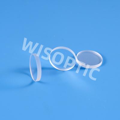
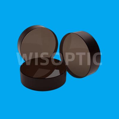
The OPO system, as illustrated in Figure 2, comprises a polarizing beam splitter (PBS), a half-waveplate (HWP), a Faraday rotator (FR), a coupling lens group (M1 and M2), cavity mirrors (M3 and M4), an MgO:PPLN crystal, a temperature-controlled oven, and a beam splitter (M5). The OPO employs an e→e+e phase-matching scheme. The PBS converts the 1064 nm pump laser output from the fiber laser into linearly polarized light; this is used in conjunction with the HWP to adjust the polarization direction to satisfy the phase-matching requirements. The distance between M1 and M2 is adjusted to focus the pump beam, thereby enhancing the power density of the pump laser, while the FR serves to isolate any returning residual pump light. The MgO:PPLN crystal (manufactured by Wisoptic Technology Co., Ltd.) measures 50 mm × 3 mm × 2 mm, features an MgO doping concentration of 5% (atomic fraction), and has a polarization period of 29.5 μm. Both end faces of the crystal are coated with anti-reflection films optimized for the wavelength ranges of 1030–1080 nm, 1380–1800 nm, and 1800–4500 nm. The MgO:PPLN crystal is mounted within the temperature-controlled oven, secured by a custom-fabricated oxygen-free copper holder; the operating temperature is set to 30 °C, with a temperature control precision of ±0.1 °C. To enhance the conversion efficiency of the MgO:PPLN-OPO, a DPSR-OPO (Doubly-Pumped Singly-Resonant OPO) operating configuration is adopted. The resonant cavity features a dual-concave structure, consisting of an input mirror (M3) and an output mirror (M4); the coating specifications for these mirrors are detailed in Table 1. Both the input mirror M3 and the output mirror M4 are plano-concave mirrors with a radius of curvature of 300 mm; the total length of the resonant cavity is 75 mm, with the MgO:PPLN crystal positioned at the center of the cavity. Under excitation by the pump light, the resonant cavity undergoes optical parametric oscillation, emitting signal and idler light; the signal and idler light are then separated one by one by the beamsplitter M5.
Fig.2 Experimental setup of OPO based on MgO: PPLN
![]()

Tab.1 Coating parameters of cavity mirror